
Max Total Assembly Video
BowFlex Max Total Assembly Video
In this video we will show you how to install the Max Total Fitness machine.
Before you begin assembly, please make sure to read the assembly manual thoroughly as it contains important safety warnings and assembly tips.
Please note that there are some steps in the assembly process that might require two people to help with the assembly.
Some components of the machine can be heavy or unwieldy. Please use a second person when doing assembly involving these parts.
Begin by Selecting an area where you are going to set up and operate your machine.
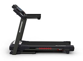
For safe operation, the machine must be located on a hard, level surface. Please allow a minimum workout area of 78.5 inches and 97 inches, as shown.
Be sure that the workout space you chose has adequate height clearance, taking into consideration the height of the user and the maximum incline of the fitness machine.
Start the Assembly by checking the parts List.
There are two boxes included with your assembly.
Box One contains the following Parts:
- Item 1: Frame (x1)
- Item 2: Shroud, Rear (x1)
- Item 3: Foot Pad Insert, (x2)
- Item 4: Foot Pad (x2)
- Item 5: Bluetooth Heartrate Armband (x1)
- Item 6: Console Assembly (x1)
- Item 7: Console Rear Cover (x1)
- Item 8: Static Handlebar Cap (x1)
- Item 9: Static Handlebar Assembly (x1)
- Item 10: Dynamic Handlebar, Left (x1)
- Item 11: Leg (x2)
- Item 12: Stabilizer Shroud, Left (x1)
Box Two contains the following parts:
- Item 13: Stabilizer Shroud, Right (x1)
- Item 14: Stabilizer Assembly (x1)
- Item 15: Pedal (x2)
- Item 16: Leveler (x4)
- Item 17: Cap (x2)
- Item 18: Rail Assembly (x1)
- Item 10: Dynamic Handlebar, Right (x1)
- Item 20: Hardware Card (x1)
- Item 18: AC Adapter (x1)
- Item 19: Manual Kit (x1)
- Item A: Socket Head Hex Screw M8x1.25x20 Black(x6)
- Item B: Lock Washer M8x14.8 Black (x6)
Check the assembly for the following hardware:
- Item C: Washer, Flat M8x18 Black (x4)
- Item D: Socket Head Hex Screw M10x1.5x25 Black (x4)
- Item E: Washer, Flat M10x23 Black (x4)
- Item F: Pan Phillips Screw M5x0.8x20 (x1)
- Item G: Washer Flat M8x24 Black (x2)
- Item H: Cap (x2)
- Item I: Wave Washer 17.2x22 (x2)
- Item J: Socket Head Hex Screw M8x1.0x55 (x4)
- Item K: Lock Nut M8 (x4)
- Item L: Flat Socket Head Hex Screw (x8)
- Item M: Socket Head Hex Screw M6x1.0x20 (x4)
- Item N: Lock Washer M6x14.8 (x10)
Please note that a right (" R ") and left (" L ") decal has been applied to some parts to assist with assembly.
Select pieces of Hardware have been provided as spares on the Hardware Card.
Be aware that after proper assembly there may be remaining Hardware
The following tools are required for assembly:
- Item O: Washer, Flat M6x13 (x4)
- Item P: Socket Head Hex Screw M6x1.0x20 (x6)
- Scissors (x1)
- 13mm Wrench (x1)
- 5mm, 6mm, 8mm #2 Hex Wrench (x1)
The following wrenches are included with your assembly:
A Number two, 5mm, 6mm, and 8mm Allen Wrench, as well as a 13mm Double Box Wrench.
Step One, Rail Assembly
For this step you will require the following parts:
- Item 1: Frame (x1)
- Item 18: Rail Assembly (x1)
- Item A: Socket Head Hex Screw M8x1.25x20 (x4)
- Item B: Lock Washer M8x14.8 (x4)
- Item C: Flat Washer M8x18 (x4)
- 13mm Wrench
You might require two people to help with the assembly process in this step.
It is highly recommended that someone assists you with this step.
Begin step one by attaching the Rail Assembly, part number 18, to the back side of the frame, part number one.
Slowly push the Rail Assembly towards the Frame and match the top holes as shown.
Next, using Four Part A Screws, four Part B lock washers, and four Part C Washers, secure the Rail Assembly to the Frame.
Place the Part C washer first, followed by the B Flat washer and Part A screws. Securely Tighten each Screw using your hand. Only Hand tighten the Hardware at this time, as you will need to fully tighten the hardware at a later step.
Finally, using the provided 13mm Double Box Wrench, release the frame from the shipping Plate by removing the hardware located on each side of the Frame
Make sure to repeat these steps for the opposite side and remove the hardware on both sides of the Frame
Step One is now complete
Step Two, Attaching the Levelers the the Stabilizer Assembly
For this step you will require the following parts:
- Item 14: Stabilizer Assembly (x1)
- Item 16: Leveler (x4)
Begin step two by attaching four Part 16 Levelers on to the Stabilizer Assembly Part Number 14.
Rotate the Levelers Clockwise to fully tighten.
Tighten all four Levelers. The levelers might require adjustment to level the Machine.
Make sure to follow the instructions in the assembly manual when leveling the Machine.
Repeat these same steps for the opposite side.
Step Two is now complete
Step Three, Attaching the Stabilizer Assembly
For this step you will require the following parts:
- Item D: Socket Head Hex Screw M10x1.5x25 Black (x4)
- 8mm Hexkey
- Item E: Washer Flat M10x23 (x4)
Begin step three by carefully lifting the Frame Assembly from the Shipping Plate.
Place the Shipping plate aside and Place the Frame on top of the Stabilizer Assembly, Part Number 14.
Matching the Frame Holes to the Top of Holes of the Stabilize Assembly, secure the Stabilizer by hand-tightening four Part D Screws and four Part E Washers.
After all hardware has been hand tightened, proceed by fully tightening the hardware using the provided 8mm Allen wrench.
Repeat these same steps for the opposite side.
Next, proceed by fully tightening ALL hardware from previous steps.
You will require the provided 6mm Allen Wrench to fully tighten the four Part A screws that were previously used on steps One.
Step Three is now complete
Step Four, Attaching the Stabilizer Shrouds to the Frame Assembly
For this step you will require the following parts:
- Item 12: Stabilizer Shroud Left (x1)
- Item 13: Stabilizer Shroud Right (x1)
Begin step four by placing the left and right Stabilizer Shrouds at the bottom near the front of the Frame Assembly.
Part Number 12 is the Left Stabilizer Shroud and Part Number 13 is the Right Stabilizer Shroud.
A right (" R ") and left (" L ") decal have been applied to the parts to assist with assembly.
Snap both Stabilizers Shrouds into place as shown.
Repeat these same steps for the opposite side.
Step Four is now complete
Step Five, Attaching the Rear Shroud and Caps
For this step you will require the following parts:
- Item 2: Rear Shroud (x1)
- Item 17: Cap (x2)
- Phillips Screwdriver (x1)
- Item F: Pan Phillips Screw, M5x0.8x20 (x1)
Begin step Five by attaching the rear shroud, part number two onto the Frame Assembly.
To attach the rear shroud, place the inside hook of the Rear Shroud on the Frame Assembly and then pivot it up into place.
Use one Part F screw to secure the Shroud. Place the screw on the top hole as shown and tighten the screw using a Phillips screwdriver.
Next, attach two Part number 17 Caps on each side of the Frame Assembly.
Gently Push each Cap into position.
Step Five is now complete
Step Six, Attaching the Legs to the Frame Assembly
For this step you will require the following parts:
- Item A: Socket Head Hex Screw M8x1.25x20 Black (x2)
- Item G: Flat Washer M8x24 Black (x2)
- 6mm Hex Wrench
- Item B: Lock Washer M8x14.8 Black (x2)
- Item H: Cap (x2)
- Item I: Wave Washer 17.2x22 (x2)
- Item 11: Leg (x2)
Begin step Six by attaching both Part 11 Legs to each side of the Frame Assembly.
Starting with the left side, place one Part I Wave-Washer through the top post as shown, before attaching the Leg.
Attach the leg to the top post and the bottom part of the leg on to the Rail Assembly.
Proceed by securing the Leg to the Frame Assembly by using One part A Screw, One Part B and one Part G Washer.
Tighten the screw by using the provided 6mm Allen wrench.
Finally, cover the hardware using one Part H Cap.
Push the cap into position.
Let the Leg rest on top of the Rail Assembly.
Be aware that the legs are connected and when either of the legs move the other does as well.
Repeat these same steps for the opposite side.
Step Six is now complete
Step Seven, Attaching the Pedals
For this step you will require the following parts:
- Item K: Lock Nut M8 (x4)
- Item 15: Pedal (x2)
- Item C: Flat Washer M8x18 (x8)
- Item J: Socket Head Hex Screw M8x1.0x55 (x4)
- 13mm Wrench
- 6mm Hex Wrench
Begin step Seven by placing two foot pedals Part Number 15, on to the Frame Assembly.
Starting with the Left Side, insert the tube ends of the Pedal on to the Leg assembly.
Be careful to avoid fingers or hands being caught or pinched.
Secure the Pedal by using Two Part J screws with Two Part C Washers on one side, and two-Part C Washers with two Part K Lock Nuts on the other side.
Fully tightening the Lock nuts using the provided 13mm Double Box Wrench tool.
Tighten the screw by using the provided 6mm Allen wrench.
Repeat these steps for the opposite side and make sure all hardware is securely tightened.
Step Seven is now complete
Step Eight, Attaching the Foot Platforms
For this step you will require the following parts:
- Item 4: Foot Pad (x2)
- Item 3: Foot Pad Insert (x2)
- Item L: Flat Socket Head Hex Screw M6x1.0x30 (x8)
- 5mm Hex Wrench
- Scissors
Begin step Eight by locating two Part 4 Foot Pads.
Before placing the foot pads onto the pedals, use a pair of scissors and cut the plastic zip ties from the pads.
Remove the zip ties and separate the food pad insert part number 3 from the foot pad.
Starting with the left side, gently place the front foot pad on to the pedal and place the food pad and insert on to the foot pad.
Slightly push the foot pad insert into place.
Repeat these same steps for the opposite side.
Next, secure the Foot Pad and Inserts using Four part L screws for each pedal.
Insert the screws through the foot pad and insert and through the pedal.
Fully tighten all screws using the provided four millimeter allen wrench.
Repeat these steps for the opposite side.
Once both platforms are tightly secured, step Eight is now complete.
Step Nine, Attaching the Static Handlebar Assembly
For this step you will require the following parts:
- Item 9: Static Handlebar Assembly (x1)
- 5mm Hex Wrench
- Item O: Flat Washer M6x13 (x4)
- Scissors
- Item N: Lock Washer, M6x13 Black (x4)
- Item M: Socket Head Hex Screw, M6x1.0x8 Black (x6)
Begin Step Nine by cutting the Shipping Zip-Tie that secures the cables inside the top Frame assembly.
Use Scissors to Cut the Zip-Tie.
Do not let the Cables drop into the Frame Assembly and take care not to cut or crimp the Console Cables.
Next, place and hold the static handlebar Assembly Part Number nine, on top of the Frame Assembly.
Before attaching the static handlebar, connect the static handlebar assembly Cables with the Frame Assembly Cables.
Make sure all cables clip and are correctly connected.
Slowly insert the static handlebar Assembly into the Frame Assembly without crimping the cables.
Secure the static handlebar Assembly using four Part M Screws, Four Part N and Part O Washers.
Hand tighten the Hardware for now.
Repeat these steps for the opposite side.
Finally after all hardware has been hand tightened fully tighten the hardware using the provided 5 millimeter allen wrench.
Repeat these steps for the opposite side.
Step Nine is now complete
Step Ten, Attaching the Console Assembly
For this step you will require the following parts:
- Item 6: Console Assembly (x1)
- Item 8: Static Handlebar Cap (x1)
- Item 7: Console Rear Cover (x1)
- Console Hardware Screws (x4)
- Phillips Screwdriver
- Console Hardware Washers (x4)
Begin Step Ten by taking off the console rear cover part number 7 from the console assembly part number 6.
Using a Phillips screwdriver loosen the hardware on the console assembly as shown.
Set the screws and washers aside at this moment
Please note that the hardware contained in the console assembly is not supplied on the hardware card.
Next connect the console assembly cables with the frame assembly cables and place the console on to the static handlebar as shown. Do not cut or crimp the cables.
Each cable connector three pin, four pin, five pin, and twelve pin has a corresponding end connector with that many openings.
After attaching all cables pivot the console assembly downwards to secure it to the static handlebar assembly.
Secure the console assembly to the static handlebar using the previously loosened hardware found in the console assembly at the beginning of the step.
Tighten the hardware using a Phillips screwdriver but take care not to over tighten the screws.
Next attach the static handlebar cap part number eight to the top of the static handlebar assembly.
Gently push the end cap into place as shown.
Finally reattach the console rear cover part number seven to the back of the static handlebar.
Step ten is now complete.
Step Eleven, Attaching the Upper Handlebars
For this step you will require the following parts:
- Item 19: Dynamic Handlebar Right (x1)
- Item 10: Dynamic Handlebar Left (x1)
- Item P: Socket Head Hex Screw M6x1.0x20 CL 12.9 Black (x6)
- 5mm Hex Wrench
- Item N: Lock Washer M6x14.8 (x6)
It is highly recommended that someone assist you with this step.
Begin step 11 by placing the left dynamic handle bar part number ten and the right dynamic handle bar part number nineteen on each side of the frame assembly.
A right R and left L decal have been applied to these parts to assist with assembly
Be aware that the pedals and the upper handlebars are connected and when either of these parts move the other does as well.
Starting with the left side secure the dynamic handlebar using three-part P screws and three-part and lock washers.
Fully tighten all screws using the provided five millimeter allen wrench.
Next repeat these steps on the opposite side and attach the right dynamic handle bar part number 19 onto the frame assembly.
Verify that all hardware has been tightly secured.
Finally be sure the upper handle bars were attached so that they are in the range of operation for the user.
Step 11 is now complete
Step Twelve, Connecting the AC Power Adapter
Begin step 12 by placing the AC adapter part number 21 to the front near the bottom of the frame assembly.
Next plug the power adapter as shown push the AC adapter into location and make sure that the power adapter wire stays clear of all moving parts.
Congratulations! You have now completed the assembly of the Max Total Fitness Machine.
Before using the machine, please make a final inspection.
You can now remove any protective covers from the face of the Console as well as the Plastic scratch guard strips from the Rails.
Please Inspect the machine to ensure that all fasteners are tight, and components are properly assembled.
Do not use until the machine has been fully assembled and inspected for correct performance in accordance with the Owner's Manual
Max Total Adjustment and Features
After assembling your new Max Total we will now show you how to move and level your machine as well as some of the key features.
Moving the machine is simple the fully assembled machine can be moved by one or more persons.
To move your machine grasp the main bar of the console assembly and carefully tilt the machine toward you onto the transport rollers located on the bottom front.
Be sure not to grab the console display while moving your machine.
Be aware of the handlebars plus the weight of the machine.
Once the machine is tilted push the machine into position and carefully lower the machine.
Please note that moving the Machine and all abrupt motions can affect the computer operation.
Once the machine has been moved to your new location you might want to level the machine if the floor on your workout area is uneven.
To adjust and level your machine loosen the locking nuts and adjust the Levellers until all four are evenly balanced in contact with the floor.
Do not adjust the Levellers to such a height that they detach or unscrew from the machine.
Finally when the machine is leveled tighten the locking nuts and ensure you have a stable machine before you use it.
Your new Max Total fitness machine comes equipped with many features.
The console features is a central component of the machine.
The console display shows the workout measurements and current options.
Please reference the assembly manual for workouts troubleshooting and other program features.
Enjoy your new Max Total fitness machine brought to you by BowFlex.